
Arithmetic Circuits
TODO
Key Concepts |
|
Terms
| Term | Meaning |
|---|---|
| Arithmetic Function/Circuit | Operation that processes input signals into a mathematical output. i.e. ADD, SUBTRACT. |
| Circuit | Group of transistors that implement logic, control, or storage capability in hardware. AKA Gate. |
| Digital Circuit | A circuit that operates on discrete binary (1/0) signals rather than continuous analog values. |
| Hardware Abstraction | Representing hardware as simplified layers, where each layer hides the complexity of the one beneath it. |
| Input/Output | Electrical or binary signals sent into or received out of a transistor, circuit, or arithmetic function. |
| Invert/Inversion | Switching a value/state to its opposite reference value/state. i.e. binary 1 is inverted into a binary 0. |
| Logic Function/Circuit | Operation that processes input signals into a boolean output. i.e. AND, OR, NOT. |
| Logic Gate | A circuit that implements a single boolean logic operation. i.e. AND, OR, NOT. |
| N-Type Transistor | Transistor that outputs the same reference/boolean value as its input. |
| P-Type Transistor | Transistor that outputs the opposite reference/boolean value than its input. |
| Ripple circuit | A set of identical circuits chained together to cause an output from one circuit feeds the next circuit, and affects the next circuit's result. Common in arithmetic circuits that require carry/borrow interactions between values. |
| Storage Function/Circuit | Operation that retains input signal (single bit) between clock cycles. i.e. STORE, RETRIEVE. |
| Transistors | Electronic devices used to represent binary 1 or 0 in hardware. |
| Truth Table | A tabular representation of a circuit's inputs and outputs. |
Introduction to Arithmetic Circuits
Performing mathematical operations is a fundamental capability for computers. In this section we review Addition and Subtraction circuits. There are other circuits to performs other basic and complex math operations.
Download the Logisim Examples collection to examine in Logisim Circuit Simulation Tool
Adder
This circuit performs addition of 2 1-bit values
Half Adder
A simplifies adder circuit handles adding 1 binary bits, producing a Sum and Carryout
The Half designation is because it does not handle a Carryin. Therefore, the Half Adder is an good circuit to learn first, but is not used in practice
| A | B | Sum | Cout |
|---|---|---|---|
| 0 | 0 | 0 | 0 |
| 0 | 1 | 1 | 0 |
| 1 | 0 | 1 | 0 |
| 1 | 1 | 0 | 1 |
Following the algorithm to create a circuit diagram from a truth table, the following circuit is created
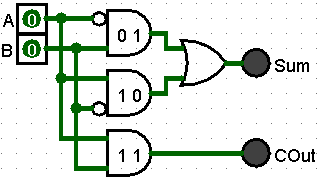
The circuit has two (2) AND gates to handle a 0,1 and 1,0 input. Both of these inputs result in a one (1) output for Sum
A Carryin only occurs when the two inputs are both 1.
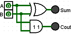
The two (2) AND gates handling 0,1 and 1,0 inputs are functioning together like an XOR gate. Therefore, we can simplify the circuit by using a single XOR gate to handle the Sum portion of the Half Adder.
Full Adder
To be useful in most situations, a Full Adder is required. It behaves like a Half Adder and includes Carryin, therefore it handles all possible inputs and outputs used to add 2 bits.
| A | B | Cin | Sum | Cout |
|---|---|---|---|---|
| 0 | 0 | 0 | 0 | 0 |
| 0 | 0 | 1 | 1 | 0 |
| 0 | 1 | 0 | 1 | 0 |
| 0 | 1 | 1 | 0 | 1 |
| 1 | 0 | 0 | 1 | 0 |
| 1 | 0 | 1 | 0 | 1 |
| 1 | 1 | 0 | 0 | 1 |
| 1 | 1 | 1 | 1 | 1 |
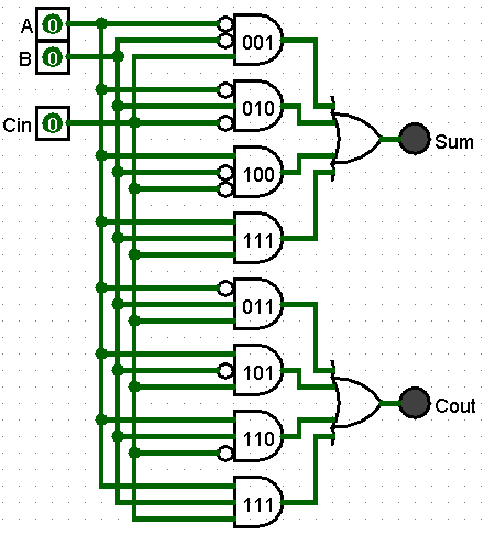
There are four (4) different possible combinations of bits added together:
- All three (3) input bits are zero (0) - Resulting in Sum 0 and Cout 0
- Only one (1) input bit is one (1) - Resulting in Sum 1 and Cout 0
- Two (2) input bits are one (1) - Resulting in Sum 0 and Cout 1
- All three (3) bits are one (1) - Resulting in Sum 1 and Cout 1
The above circuit has 2 sets of redundant AND gates (101 and 111). The circuit diagram simplifies to the following
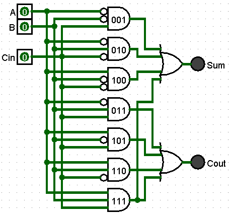
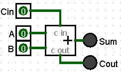
Full Adders have a simplified component symbol with the same 3 inputs and 2 outputs.
Rippler Adder
Connecting a series of Full Adders creates a circuit that will add two (2) multi-length bit strings together. The term Ripple denotes how the Carryin and Carryout of individual Full adders are chained together, connecting a Carryout from a less significant bit place to the next most significate bit's Carryin. The Carry results Ripple thought the circuit quickly (in the same clock cycle) to produce the sum of all the bits.
The Carryout from the last Full Adder is considered Overflow for a 4-bit system. It may set a flag for the program to check. It may connect to a Carryin of another 4-bit Ripple Adder circuit.
Note the initial Carryin (to the least significant bits being added) is hard-coded to zero (0). This first Adder is functionally a Half adder. However, circuit designers prefer all parts be the same, so in practice all Adders are Full adders.
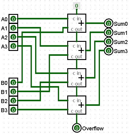
Four (4) bits in the A bit string (designated by A3A2A1A0) are added to the Four (4) bits in the B bit string (designated by B3B2B1B0)
Each An and Bn bit are input into a Full adders. The Carryout from the previous Full Adder feeds into the Carryin of this Full Adder. The An is output.
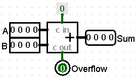
Ripple Adders can be shown on a circuit diagram with multi-bit inputs and outputs
Subtractor
Half Subtractor
Like the Half Adder, the Half Subtractor does not handle the third inputs value, Borrowin.
| A | B | D | Bout |
|---|---|---|---|
| 0 | 0 | 0 | 0 |
| 0 | 1 | 1 | 1 |
| 1 | 0 | 1 | 0 |
| 1 | 1 | 0 | 0 |
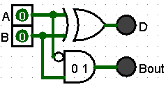
Following the algorithm to create a circuit diagram from a truth table, the following circuit is created
Reading a line from the truth table is A - B = D, Bout was borrowed from the higher significant value.
Line 2: 0 - 1 = 1 after borrowing 1
  1 0        0 10 (borrowed 1 from 2's column)
- 0 1  ->  - 0 1
  ---        ---
             0 1
The circuit has two (2) AND gates to handle 0,1 and 1,0. Both of these inputs result in a one (1) for the Difference output.
A third AND gate handles 0, 1 input that outputs a one (1) for Borrowout.
The circuit contains to two (2) AND gates for inputs 0, 1. IT can be simplified by removing the redundant AND gate and connecting the output to Borrowout
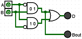
Like the Hald Adder, the two (2) AND gates handling 0,1 and 1,0 inputs are functioning together like an XOR gate. Therefore, we can simplify the circuit by using a single XOR gate to handle the Sum portion of the Half Adder.
Full Subtractor
The missing input, Bin, is added to the truth table to make if a Full Subtractor. This input is 1 if the previous column (1 step less significant) had to borrow from this column
| A | B | Bin | D | Bout |
|---|---|---|---|---|
| 0 | 0 | 0 | 0 | 0 |
| 0 | 0 | 1 | 1 | 1 |
| 0 | 1 | 0 | 1 | 1 |
| 0 | 1 | 1 | 0 | 1 |
| 1 | 0 | 0 | 1 | 0 |
| 1 | 0 | 1 | 0 | 0 |
| 1 | 1 | 0 | 0 | 0 |
| 1 | 1 | 1 | 1 | 1 |
This is a Full Subtractor created using the algorithm and it has been simplified.
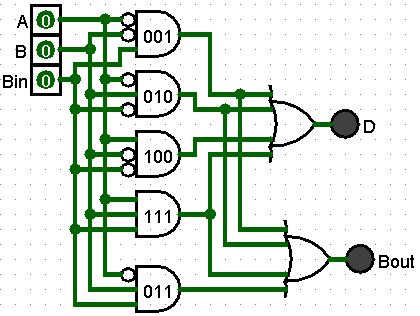
Three (3) of the AND gates from the D circuit are the same for the Bout, 001, 010, and 111.
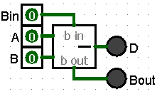
Full Subtractors have a simplified component symbol with the same 3 inputs and 2 outputs.
Rippler Subtractor
Like the Adder, Subtractors can be connected in series for create a multi-bit subtraction circuit. The 4-bit inputs and outputs work the same as the Adder
The Borrowout from the last Full Subtractor is considered Underflow for a 4-bit system. It may set a flag for the program to check. It may connect to a Borrowin of another 4-bit Ripple Subtractor circuit.
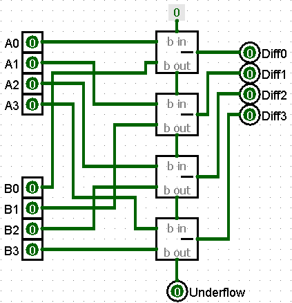
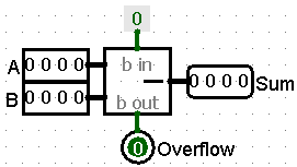
Ripple Subtractor can be shown on a circuit diagram with multi-bit inputs and outputs
Conclusion
Single-bit addition and subtraction circuits are combined into multi-bit circuits that cas operate on multiple bit strings. And, these complex circuits can carry an borrow when needed.
The Ripple effect of information flowing though these complex circuits quickly settle out to produce a final answer.