
Truth Tables
TODO
Key Concepts |
|
Terms
| Term | Meaning |
|---|---|
| Arithmetic Function/Circuit | Operation that processes input signals into a mathematical output. i.e. ADD, SUBTRACT. |
| Circuit | Group of transistors that implement logic, control, or storage capability in hardware. AKA Gate. |
| Digital Circuit | A circuit that operates on discrete binary (1/0) signals rather than continuous analog values. |
| Hardware Abstraction | Representing hardware as simplified layers, where each layer hides the complexity of the one beneath it. |
| Input/Output | Electrical or binary signals sent into or received out of a transistor, circuit, or arithmetic function. |
| Invert/Inversion | Switching a value/state to its opposite reference value/state. i.e. binary 1 is inverted into a binary 0. |
| Logic Function/Circuit | Operation that processes input signals into a boolean output. i.e. AND, OR, NOT. |
| Logic Gate | A circuit that implements a single boolean logic operation. i.e. AND, OR, NOT. |
| N-Type Transistor | Transistor that outputs the same reference/boolean value as its input. |
| P-Type Transistor | Transistor that outputs the opposite reference/boolean value than its input. |
| Ripple circuit | A set of identical circuits chained together to cause an output from one circuit feeds the next circuit, and affects the next circuit's result. Common in arithmetic circuits that require carry/borrow interactions between values. |
| Storage Function/Circuit | Operation that retains input signal (single bit) between clock cycles. i.e. STORE, RETRIEVE. |
| Transistors | Electronic devices used to represent binary 1 or 0 in hardware. |
| Truth Table | A tabular representation of a circuit's inputs and outputs. |
Introduction to Truth Tables
We start with a tool to describe logic functions
The Truth Table is a notation that shows binary inputs and resulting outputs for a logic circuit. The circuit can be a basic circuit (with 2 inputs and 1 output) or a complex circuit made up of many individual logic devices.
All truth tables, and the devices they describe will have a set of inputs, the circuit that modifies the inputs, and the outputs. For simplicity, outputs are consider instantaneously generated when the inputs are applied.
Anatomy of a Truth Table
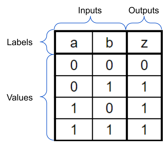
Inputs and Outputs are labeled with letters. The labels typically do not have any meaning associated with the inputs/outputs.
Inputs and Outputs have values as signals in and out of the device being describes by the truth table.
All inputs in a given row are applied to the circuit and product the given output.
In the above example:
when a inputs a 0 and b inputs a 0, the z output will be 0
when a inputs a 0 and b inputs a 1, the z output will be 1
when a inputs a 1 and b inputs a 0, the z output will be 1
when a inputs a 1 and b inputs a 1, the z output will be 1
Complex Circuits
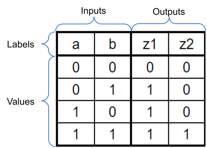
Truth tables can have more than 2 inputs and 1 output. In cases of multiple outputs, all inputs in a given row produce each output signal separately
In the above example:
when a inputs a 0 and b inputs a 0, the z1 output will be 0 and z2 output will be 0
when a inputs a 0 and b inputs a 1, the z1 output will be 1 and z2 output will be 0
and so on
You can also make the above truth table 2 separate tables
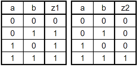
When creating a physical circuit based on this diagram, remember this is one circuit and the a and b inputs are from the same source
We will learn how to crate physical circuits, using a virtual circuit design adn simulation tool later
Conclusion
Using Truth Tables, we can understand how different inputs produce different outputs in the circuit being described
Reading a single row os a truth table, we see all the input values into the circuit and the expected output(s)
If a circuit/truth table produces multiple outputs, each row of inputs will product the expect outputs separately