Basic Logic Circuits
Creating Simple Logic Circuits using Transistors
Key Concepts |
|
Terms
| Term | Meaning |
|---|---|
| Arithmetic Function/Circuit | Operation that processes input signals into a mathematical output. i.e. ADD, SUBTRACT. |
| Circuit | Group of transistors that implement logic, control, or storage capability in hardware. AKA Gate. |
| Digital Circuit | A circuit that operates on discrete binary (1/0) signals rather than continuous analog values. |
| Hardware Abstraction | Representing hardware as simplified layers, where each layer hides the complexity of the one beneath it. |
| Input/Output | Electrical or binary signals sent into or received out of a transistor, circuit, or arithmetic function. |
| Invert/Inversion | Switching a value/state to its opposite reference value/state. i.e. binary 1 is inverted into a binary 0. |
| Logic Function/Circuit | Operation that processes input signals into a boolean output. i.e. AND, OR, NOT. |
| Logic Gate | A circuit that implements a single boolean logic operation. i.e. AND, OR, NOT. |
| N-Type Transistor | Transistor that outputs the same reference/boolean value as its input. |
| P-Type Transistor | Transistor that outputs the opposite reference/boolean value than its input. |
| Ripple circuit | A set of identical circuits chained together to cause an output from one circuit feeds the next circuit, and affects the next circuit's result. Common in arithmetic circuits that require carry/borrow interactions between values. |
| Storage Function/Circuit | Operation that retains input signal (single bit) between clock cycles. i.e. STORE, RETRIEVE. |
| Transistors | Electronic devices used to represent binary 1 or 0 in hardware. |
| Truth Table | A tabular representation of a circuit's inputs and outputs. |
Introduction to Basic Logic Circuits
Introduction to Logic Gates - Kevin Drumm - UK YouTube Provider
This is a beginner's introduction to logic gates. It starts with an historical mention of the development of two state devices including valves and transistors, and how these led to the silicon chip. It then goes on to describe the nature and behaviour of the three main logic gates NOT, AND and OR in terms of electrical voltages, binary digits (bits) and truth tables.
Copyright TODO
Simple Logic Circuits
Basic logic operations
NOT
| a | b |
|---|---|
| 0 | 1 |
| 1 | 0 |

Applying NOT to something typically means considering the opposite of the original things.
If the crowds are NOT too big, we will go to the park.
In this example we are considering (or hoping) for the opposite of a big crowd.
When applied to binary values, the opposite means switching the bits to their opposite values. We will refer to this as flipping the bits. We also refer to this as Negation as it negates or reverses the bits.
NOT is the only operation we will discuss that takes 1 input. It operates on a single bit and flips.
NOR
NOR Truth Table
| a | b | a OR b | NOT(a OR b) |
|---|---|---|---|
| 0 | 0 | 0 | 1 |
| 0 | 1 | 1 | 0 |
| 1 | 0 | 1 | 0 |
| 1 | 1 | 1 | 0 |
NOR is referred to as NOT OR. It negates the results of the OR output. In effect it only output a 1 if both inputs are 0
NOR is effectively feeding the output of an OR operation into a NOT operation. It is interesting that the result is 0 unless both inputs are 0
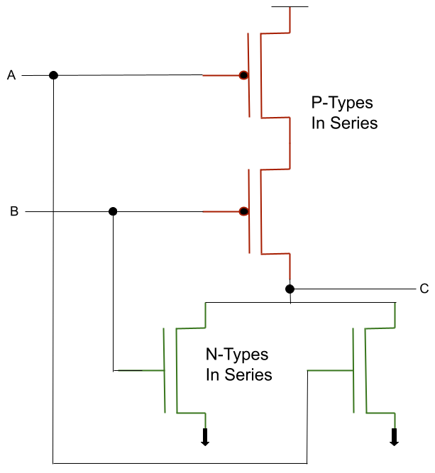
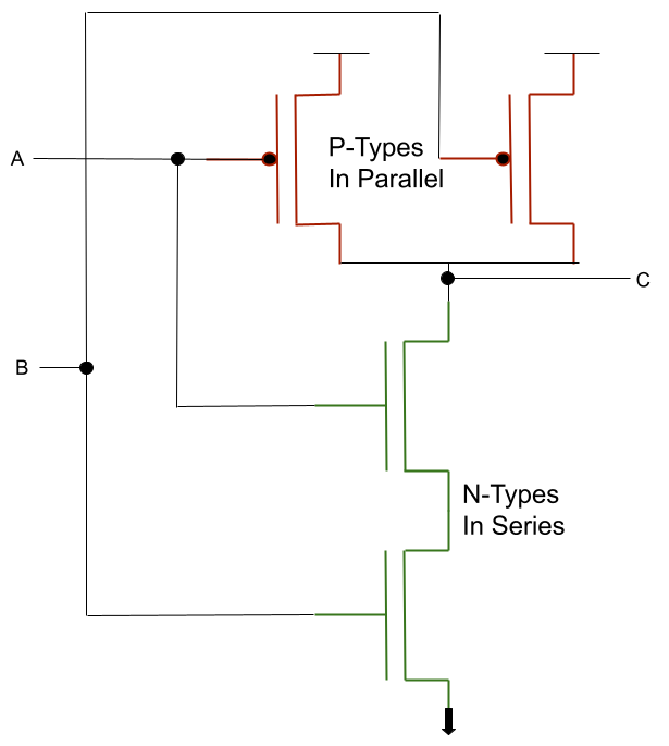
NOR Transistors
NOR Gate
We simplify the transistor diagram into a simple circuit symbol.
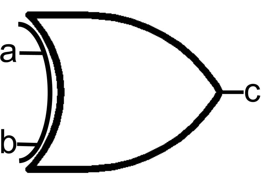
OR
OR Truth Table
| a | b | c |
|---|---|---|
| 0 | 0 | 0 |
| 0 | 1 | 1 |
| 1 | 0 | 1 |
| 1 | 1 | 1 |
OR Transistors
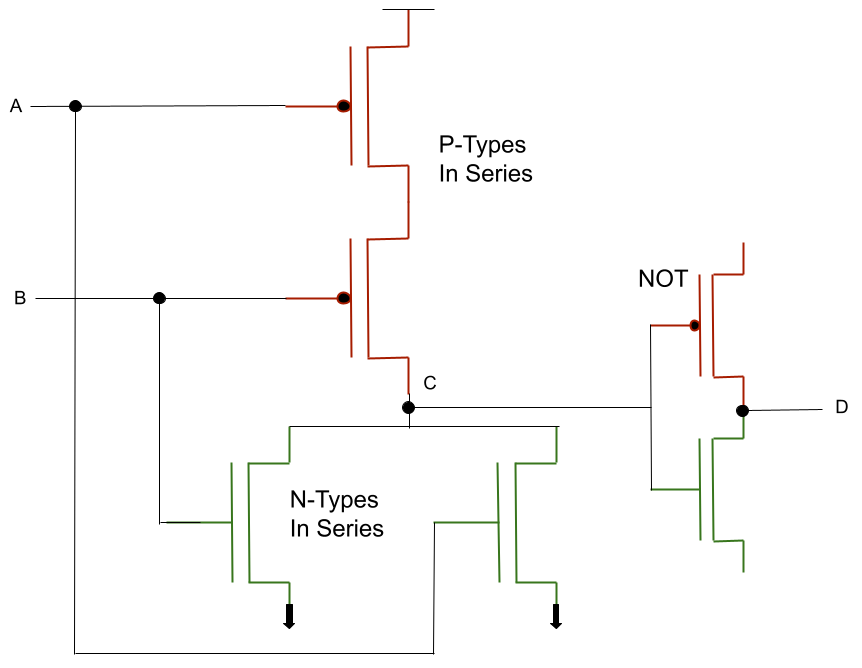
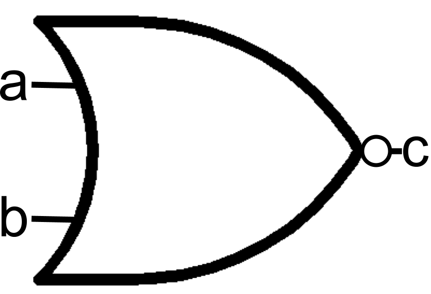
OR Gate
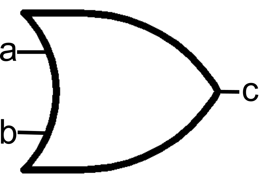
We simplify the transistor diagram into a simple circuit symbol.
Applying OR to something typically means considering any one situation enough to lead to the outcome.
We will go to the park if traffic is not too bad OR I we can get an Uber
In this example 1 or two things must be true: either traffic is low or there is an alternative way to get to the destination without driving in heavy traffic. It is also true it both things are true
When applied to binary values, OR compare two bits. If either bit is 1 the result to 1. Also, both bits can be 1 to product a 1 result. The only case that ORing 2 bits results in 0 is when both bits are 0. In the above real-life if traffic was heavy and there were no Uber rides available, the park trip is cancelled
NAND
NAND is referred to as NOT AND. It negates the results of the AND output. In effect it only output a 0 if both inputs are 1
It is not a common logic operation applied to everyday situation, but it has utility in the logic and computer circuits
NAND Truth Table
| a | b | c |
|---|---|---|
| 0 | 0 | 1 |
| 0 | 1 | 1 |
| 1 | 0 | 1 |
| 1 | 1 | 0 |
It is interesting that the result is 1 unless both inputs are 1
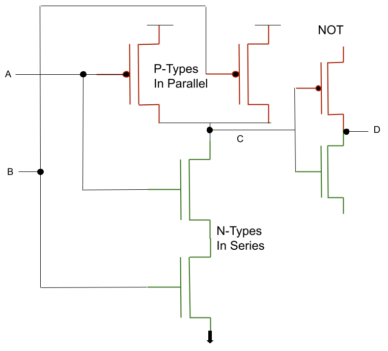
NAND Transistors
The NAND circuit requires 2 P-Type transistors in parallel and 2 N-Type transistors in series. a and b inputs are connected to one of the P- and N-Type transistor control inputs. In this configuration, the junction between the P- and N-Type pairs outputs the NAND logic.
NAND Gate
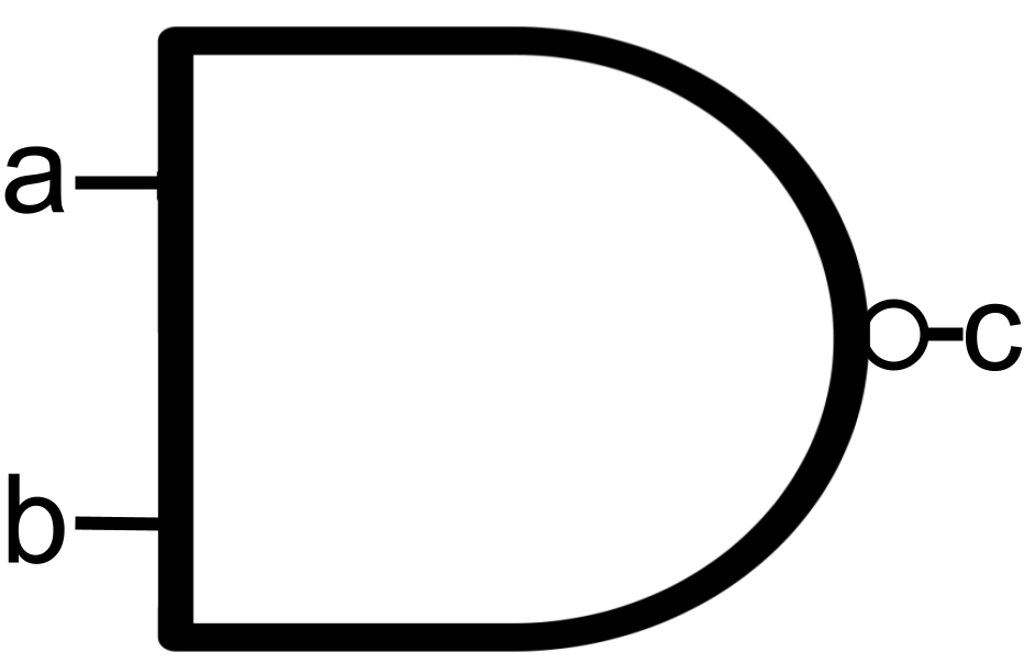
We simplify the transistor diagram into a simple circuit symbol.
AND
Applying AND to something typically means considering all situations must occur to lead to the outcome.
We will go to the park if traffic is not too bad AND I we can get an Uber
In this example both things must be true: traffic is low as well as there is an alternative way to get to the destination without driving in heavy traffic. If either one of the things is not true then no park trip. If both things are not true, the trip is also off
AND Truth Table
| a | b | c |
|---|---|---|
| 0 | 0 | 0 |
| 0 | 1 | 0 |
| 1 | 0 | 0 |
| 1 | 1 | 1 |
AND Transistors
AND Gate
 We simplify the transistor diagram into a simple circuit symbol
 When applied to binary values, AND compare two bits. If either bit is 0 the result to 0. If 1 bit is 0 and the other is 1 to product is also 0 result. The only case that ANDing 2 bits results in 1 is when both bits are 1. In the above real-life if traffic was heavy or there were no Uber rides available, the park trip is cancelled
XOR
| a | b | c |
|---|---|---|
| 0 | 0 | 0 |
| 0 | 1 | 1 |
| 1 | 0 | 1 |
| 1 | 1 | 0 |
XOR is referred to as Exclusive OR. The difference between XOR and OR is the case where both bits as 1 results in 0. Another way to think of this is the two bits being compared must be different to result in 1
Logic Circuit Constructs
There are a couple of interesting things simple logic circuits can do to be made more versatile or to change their behavior.
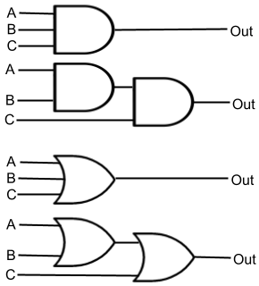
Adding Inputs to a Logic Circuit
At this point all of our logic circuits have 2 inputs (with the exception of NOT). It is possible to have a logic circuit with more than two (2) inputs.
While the diagram for a 3 or 4 input AND circuit seems simple, under-the-hood it is a set of 2-input AND circuits with the output of 1 feeding an input of the next. The logical behavior still works as expected.
DeMorgan's Laws
Augustus De Morgan proposed a pair of comparisons in the field of boolean algebra that have an interesting application to computer organization. When applying negation (NOT) transformations to solution sets of AND and OR functions, he realized that negating inputs and output of one set resulted in the other.
Inverting the inputs to an OR gate, then inverting the output produces the same truth table as an AND gate.
| a | b | NOT a | NOT b | NOT a AND NOT b | NOT(NOT a AND NOT b) | a OR b |
|---|---|---|---|---|---|---|
| 0 | 0 | 1 | 1 | 1 | 0 | 0 |
| 0 | 1 | 1 | 0 | 0 | 1 | 1 |
| 1 | 0 | 0 | 1 | 0 | 1 | 1 |
| 1 | 1 | 0 | 0 | 0 | 1 | 1 |

Inverting the inputs to an AND gate, then inverting the output produces the same truth table as an OR gate.

So, with only NOT and OR gates, you can produce a circuit that outputs AND results. Using NOT and AND gates will, similarly produce OR outputs.
Conclusion
Simple logic circuits are constructed of transistors. They behave like the boolean logic operations. AND, OR, and NOT are the core logic circuits. Variations of these circuits include NAND, NOR, and XOR
Two (2) input circuits can be constructed to allow additional inputs into the logic calculation. By manipulating input and output signals, one logic circuit can be made to change it's behavior.