The Transistor
TODO
Key Concepts |
|
Terms
| Term | Meaning |
|---|---|
| Arithmetic Function/Circuit | Operation that processes input signals into a mathematical output. i.e. ADD, SUBTRACT. |
| Circuit | Group of transistors that implement logic, control, or storage capability in hardware. AKA Gate. |
| Digital Circuit | A circuit that operates on discrete binary (1/0) signals rather than continuous analog values. |
| Hardware Abstraction | Representing hardware as simplified layers, where each layer hides the complexity of the one beneath it. |
| Input/Output | Electrical or binary signals sent into or received out of a transistor, circuit, or arithmetic function. |
| Invert/Inversion | Switching a value/state to its opposite reference value/state. i.e. binary 1 is inverted into a binary 0. |
| Logic Function/Circuit | Operation that processes input signals into a boolean output. i.e. AND, OR, NOT. |
| Logic Gate | A circuit that implements a single boolean logic operation. i.e. AND, OR, NOT. |
| N-Type Transistor | Transistor that outputs the same reference/boolean value as its input. |
| P-Type Transistor | Transistor that outputs the opposite reference/boolean value than its input. |
| Ripple circuit | A set of identical circuits chained together to cause an output from one circuit feeds the next circuit, and affects the next circuit's result. Common in arithmetic circuits that require carry/borrow interactions between values. |
| Storage Function/Circuit | Operation that retains input signal (single bit) between clock cycles. i.e. STORE, RETRIEVE. |
| Transistors | Electronic devices used to represent binary 1 or 0 in hardware. |
| Truth Table | A tabular representation of a circuit's inputs and outputs. |
Introduction to the Transistor
Transistors are electronic devices constructed to control or amplify electrical input. In computer organization, we are interested in the control version as they will represent the 1 and 0 values of binary numbers
There are 2 general types of transistors used in computer hardware. They are made of silicon and one (1) of two (2) different add-in materials. Silicon mixed with one (1) add-in causes a particular switch behavior. Mixed with the other add-in, the transistor behaves with the opposite switch action.
How semiconductors work - Ben Eater - UK YouTube Provider
A detailed look at semiconductor materials and diodes..
Copyright TODO
Video: How Semiconductors Work — Text Alternative
This video describes how semiconductor materials work at the atomic level. Key concepts covered:
- Silicon is "doped" with small amounts of other elements to alter its electrical properties
- N-type silicon: excess electrons (negative charge carriers) allow current to flow freely
- P-type silicon: electron "holes" (positive charge carriers) where electrons are missing
- When N-type and P-type silicon are joined they form a P-N junction (diode) that permits current to flow in one direction only
- This one-directional property is the foundation of transistor switching behavior
Video: How Transistors Work as Binary Switches — Text Alternative
This video builds on semiconductor concepts to show how transistors function as binary switches. Key concepts covered:
- A transistor layers N-type and P-type silicon into a three-layer NPN (or PNP) sandwich
- The middle base layer is the control; the outer collector and emitter layers carry the main current
- A small control voltage at the base determines whether current flows between collector and emitter
- High control voltage: current flows — transistor is on (binary 1)
- Low control voltage: no current flows — transistor is off (binary 0)
- This on/off switching is how transistors physically represent the binary digits 0 and 1 in digital circuits
The first video describe the movement of electrons through the two (2) silicon mixtures to act as a diode. The second video builds on the first, showing how a three-layer sandwich of doped silicon behaves like a binary 0 or 1.
It is not within the scope of this course, but is a great description of how electrons move through silicon materials. If you are interested in understanding transistors at the lowest levels, check it out
P- and N-Type Transistors
Semiconductor transistors act as switches in the core of modern computers. Constructed with layers of slight variations of silicon (mixed or doped with other elements). Transistors have a control connector that provides an input into the device. The input voltage will cause the transistor to output 1) the same voltage as its input, or 2) the opposite of its input voltage
There are two (2) types of basic transistors:
- P-Type output the opposite of its input
- N-Type output the same as its input
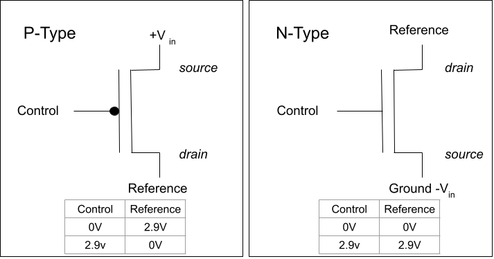
Above a P-Type with 2.9 volts input on the Control line to output 0 volts on the Reference line.
N-Type transistors output 0 volts with 0 volts are input, and 2.9 volts out when 2.9 volts are input.
The line from source to drain is one independent electrical connection. there is a power source (not pictured) that connects these 2 lines.
The Control line also has another line that connects both to a power source. It is omitted from these diagrams for simplicity. In truth, the two electrical connections (source to drain and Control to the missing ground connection) typically share a ground or common. The two connections still operate separately
TIP
The P-Type symbol includes a circle where the Control line meets the Reference line. A circle symbol indicates opposite or inverse.
Also, source and drain lines are swapped between P- and N-Type diagrams. Finally, the Vin is positive for P-Types and negative for N-Type. This is related to electrical difference, and beyond the scope of our class.
Transistors as Bits
Transistors use a voltage input to switch another voltage output. Voltage are analog quantities, meaning there are (until we start looking at the level os the electron) an infinite number of different voltage level or amounts.
Binary values are digital. The have 2 distinct values and nothing in between. At the lowest level, binary values are 1 or 0. There is no 0.5 binary value.
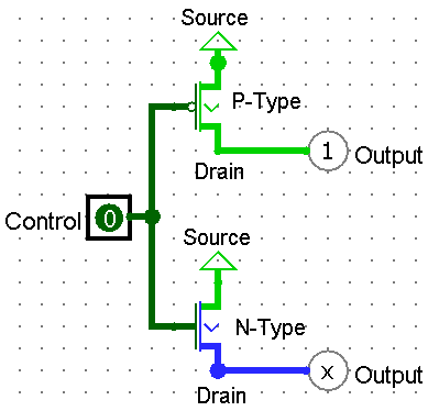
Download the Logisim Examples collection to examine in Logisim Circuit Simulation Tool
To use analog transistors to represent digital bits, hardware designers must consider the rise/fall time of transistors. Essentially, then a transistor is first set to on or 1, it will take a very short time for the voltage in the transistor to rise to a level that is on or 1.
We will refer to rise and fall time intervals generally as settle time. This is the time required for a transistor (or a circuit made is similar transistors) to change from one state to the other.
Likewise, when a transistor it set ot off or 0, there is brief fall time where the voltage dissipates from the transistor.
The purpose of the clock in modern computers is to orchestrate the settle time of all transistors in the system. It synchronizes part of the hardware to send control signals with the transistors that receive the control signals. During a part of a clock cycle, control signals are send out to transistors. During another part of the clock system, activity is prevented so those transistors have time to settle.
The clock cycle provides other essential duties in modern computer hardware. In computer organization, we rely on it to keep transistors synchronized to maintain reliable binary values.
CPU and motherboard manufactures must match the settle time for the transistors with a clock speed that allows
TIP
Considering the clock keeps all the transistors (and other things) synchronized, what happens when a computer modder increases the clock speed beyond the manufacturer's recommendations
How would transistors react to having less settle time?
What might happen to circuits that are sending or receiving bits from these transistors?
Conclusion
Silicon materials can be used to hold voltages. The voltages control the state of a bipolar device. The P- and N-Type bipolar devices (transistors) are used in modern computers to represent the digital 1 and 0 values in the binary number system.
A clock is used to ensure all transistors have the time to transition between states.