Instruction Anatomy
Key Concepts |
|
Terms
| Term | Meaning |
|---|---|
| ALU | The arithmetic and logic unit (ALU) is a component in the CPU that preforms mathematic and logical functions. |
| Branching | A technique that causes a program to change the flow of its execution; e.g., if/else and calling a function. |
| Clock Cycle | A single time segment, controlled by the computer's clock, in which circuits receive input values, process the inputs, and then produce an output. |
| Condition Code (CC) | Information about the previous instruction's result. Can indicate that the previous instruction resulted in an error/exception, overflow/underflow, or positive/zero/negative value |
| FDE Cycle | The Fetch-Decode-Execute pattern used by the CPU to execute a single instruction. |
| Instruction | Single executable line of code in a program. Contains OpCode and Operands. |
| ISA | Instruction Set Architecture. LIst of all Instruction OpCode and expected Operands. |
| Memory | Storage used by the program to save and retrieve data. This storage is external to the CPU. |
| OpCode | Assembly instruction keyword as defined by the ISA. |
| Operand(s) | Assembly instruction parameters, as defined by the ISA. |
| Register | Storage used by the CPU to save and retrieve data. These devices directly connected to the CPU's control device and the ALU. |
| Subroutines | Subset of branching that has added capabilities like passing parameters, throwing exceptions, and returning results. |
| TRAP Routines | Functions that are built-in to the programming language; e.g., System.out.println() in Java. |
Introduction
All commands are 16-bits in length. The bits are partitioned into OpCodes and Operands. During execution of an LC-3 command, the Simulate's control unit examines the instruction (which was loaded into the IR at the start of execution)
The control unit parses the 16-bits of the IR and causes the system to preform a series of steps to complete execution of that command.
The number of clock cycles required to complete a command will vary with the steps needed to complete it
Opcodes and Operands

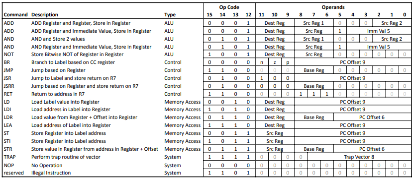
Bits [15,12] of each 16-bit command are the OpCode. This 4-bit string is unique for each command.
Bits [11,0] are the Operands (parameters) for each Opcode/Command. Depending on the command, some bits of the Operands are not used, and left as zero (0).
The LC-3 ISA defines the commands, and each bit in the command string that the Simulate environment will reference to execute each command.
Opcode
During the execution of a command, Simulate loads the new command into the IR. It will use the IR to determine the OpCode and, later in the command execution, Operands needed to complete the command.
Why are Operands determines later in the command execution?
Reviewing the commands, above, notice that some commands use the 12-bit Operand portion of the command different than others.
Some are the same, but others are different.
The Control Unit (from von Nuemann's Model) that orchestrates the execution of each command cannot parse the Operands until it knows the Opcode. From the OpCode, the Control Unit can correctly parse the remaining 12 bits of the IR into the correct parameters to execute the command as the programmer intended.
Operands
The remaining 12 bits are parsed based on the OpCode. The control unit extracts the important bits into information used to complete the command
Dest Reg
Commands that store results in a register use 3 bits to identify the register
Src Reg / Src Reg 1 / Src Reg 2
Commands that read data from a register use 3 bits to identify the register. Commands that use two (2) source registers are notes with 1 and 2.
Imm Val
Immediate values are hard-coded numbers that are assembled directly into the command. The LC-3 has a special mode for immediate values in the ADD and AND commands.
Base Reg
A 3-bit address of a general register that contains a base value for some Load/Store commands
PC Offset
A 6- or 9-bit value that is added to the PC register for Load/Store and Branch instructions.
Trap Vector
An 8-bit value of a built-in TRAP function. This value is the memory address of a lookup table to the actual TRAP function.
Referencing Registers
Recall that the LC-3 has eight (8) general registers that user programs and Simulate share. In assemble source code, the registers are identified by "R" and a number (i.e. R3, R7).
Src, Dest, and Base Registers included in Operands are all 3-bit values. The 3 bits address the register to be used in the Operands.
| Source Code | Operand |
|---|---|
| R0 | 000 |
| R1 | 001 |
| R2 | 010 |
| ... | ... |
| R7 | 111 |
Processing a Command
During the execution of a single command, the control unit will direct a series of events during several clock cycles. These events will cause the command to be loaded into the IR, Operands to be moved to/from memory, register values to be loaded into the ALU, and many more.
Performs in the correct order, these events will result in the command execution to complete correctly.
There are seven (7) possible events that can occur. Some commands do not require all seven (7) events to occur.
All commands will require Fetch, Decode, and Execute events. Some commands will also require some or all of the other events.
This processing from the command unit is commonly called the Fetch-Decode_Execute cycle of an instruction.
If performed, the events are always performed in the following order:
Fetch
- Load the command into the IR
- Transfer the current PC to the Memory Interface
- Wait for the Memory Interface to retrieve the data
- Transfer the resulting data from the Memory Interface to IR
- Add 1 to the PC
- Increment PC by 1
Recall that the PC contains the address of the next command to execute. At the start of Fetch, that address in PC is passed to the Memory Interface. After a few clock cycles, the Memory Interface will have the data (the next command) from that address.
The data is copied into the IR. The control unit has the command's 16 bits to parse and execute.
In preparation for the command needed for the next cycle, the PC in incremented. It now has the address of the next command needed after this command is executed.
Decode
- Use the IR[15,12] (the Opcode) to lookup the mapping of the Operand bits [11,0]
- Decode each Operand of the current command for later use
The control unit uses the Opcode to find all the Operands for thew current command. Recall that the meaning of bits [11,0] varies based on the command/Opcode.
Evaluate Addresses
Optional Event only used if the current command is a Load command or TRAP
- Based on the specific Load instruction, calculate the address to load using Base Reg, PC Offset, and/or Trap Vector Operands
- Retain the resulting address for the next event
If the Opcode will load data from Memory -or- is the TRAP instruction, the control unit must use sections of the Operands to calculate a 16-bit address from which to read data
- For PC Offset Operands, the address in the PC to added to the PC Offset
- For Base Reg Operands, the data in the general register identified in the Base Reg Operand is extracted
- For TRAP instruction, the Trap Vector Operand (sign extended to 16-bits) is extracted.
Fetch Operands
Optional Event only used if the current command is a Load command or TRAP
- Load data from Memory
- Transfer the previously derived address to the Memory Interface
- Wait for the Memory Interface to retrieve the data
- Retain the resulting data for the next event
The control unit reads data from memory in preparation to execute the command.
For TRAP commands, the data returned from the Memory Interface is the address of the first instruction of the referenced TRAP instruction.
Execute
- Complete the command execution, based on the Opcode
- For ALU Commands
- Transfer data from Registers to the ALU
- Signal ALU to perform specific operation
- Transfer result to the specified Register
- Set CC based on result
- For Load Commands
- Transfer the previously loaded data into the specified Register
- Set CC based on value loaded
- For Branch Commands
- Compare CC register to command's Operands
- If the same, copy the previously calculated address to the PC
- For Jump Commands
- Copy PC to Register 7
- Copy previously calculated address to PC
- For RET Command
- Copy R7 to PC
- For TRAP commands
- Copy the previously calculated address to the PC
- For ALU Commands
Store Results
Optional Event only used if the current command is an ALU or Store command
- Complete the command execution, based on the Opcode
- For ALU Commands
- Transfer result to the specified Register
- Set CC based on result
- For Store Commands
- Transfer the destination address and data to the Memory Interface
- Wait for Memory Interface to complete
- For ALU Commands
Conclusion
Assembly instructions are made up of bit patterns that define the instruction (opcode) and parameters (operands). All LC-3 instructions are 16 bits in length, with the first 4 bits defining the opcode. The remaining bits can be used to identify data or modes used for that opcode
Not all 16 bits are used in every instruction.
The controller in the CPU requires multiple cycles to execute a single instruction. The number of cycles depends on the instructions. Simpler instructions take less cycles
All ISAs follow a Fetch-Decode-Execute cycle to complete each instruction. Some instructions include additional steps, typically to interface to memory for data management.
