
TRAP Routines
Built-in code for common operation
Key Concepts |
|
Terms
TRAP vector — A numeric code passed to the TRAP instruction that indexes into a jump table. The jump table entry at that address holds the starting address of the corresponding TRAP routine's code. For example, TRAP x25 (HALT) uses vector x25.
System call — A request from a user program to the operating system (or, in LC-3, to built-in TRAP routines) to perform a privileged service such as reading keyboard input or writing a character to the display. The program provides inputs in specific registers, calls the routine, and reads results from registers after it returns.
Introduction to TRAP Routines
The LC-3 provides a few built-in functions to make the system easier to use. These are common routines that typical programs might use, and is provided so a programmer does not need to write their own code
LC-3 provides 2 User Input and 3 User Output TRAP routines, as well as the HALT routine to terminate execution
LC-3 TRAP Routines
The LC-3, designed as a teaching ISA, includes TRAP functions to support general keyboard input and terminal output
| OpCode | unused | trapvect8 |
|---|---|---|
| 1111 | 0000 | -------- |
Examples
TRAP x23 ; Call IN trap routine
IN ; Call IN trap routine
Calling these routines in user code can take 1 of 2 different forms:
  ; These two lines call the same TRAP code
  TRAP x20  ; Get character from console
GETC ; Uses assembler shortcut for TRAP x20Note that the address in the 1st example is the TRAP Vector, not the Code Address. This is because LC-3 uses a Vector or Jump Table to look up the address of the first line of the actual TRAP code
| TRAP Vector | Code Address | Assembler Shortcut | Purpose | Result |
|---|---|---|---|---|
| x0020 | x0400 | GETC | Read one input character from the keyboard and store it into R0 without echoing the character to the console | After execution, R0 contains the ascii code for the character entered in the console |
| x0021 | x0430 | OUT | Output character to the console | Before execution, load R0 with ascii code to display in console |
| x0022 | x0450 | PUTS | Output null terminating string to the console | Load address (using LEA) of first character of the string to display |
| x0023 | x04A0 | IN | Displays a prompt and reads one input character from the keyboard and store it into R0 and echo the character to the console | After execution, R0 contains the ascii code for the character entered in the console |
| x0024 | x04E0 | PUTSP | Same as PUTS except that it outputs null terminated strings with two ASCII characters packed into a single memory location, with the low 8 bits outputted first then the high 8 bits | Load address (using LEA) of first character of the string to display |
| x0025 | xFD70 | HALT | Ends a user’s program | None. But does modify registers while executing and does not return |
Routines
TRAP x20 / GETC
Reads a single character from the keyboard. The character is not echoed to the displays.
The ASCII value of the pressed key is placed in R0 before returning to the user code
.ORIG x3000
  TRAP x20 ; Get a single charater and store in R0
  HALT
.END.ORIG x3000
GETC ; Get a single charater and store in R0
HALT
.ENDTRAP x21 / OUT
Writes a character from R0 to the display. R0 must contain the ASCII value of the character to display.
.ORIG x3000
  LD R0, MyChar	 ; Load 'A' into R0
  TRAP x21 	 ; Print 'A' to display
  HALT
MyChar .FILL x65 ; acscii 'A'
.END.ORIG x3000
LD R0, MyChar ; Load 'A' into R0
OUT ; Print 'A' to display
HALT
MyChar .FILL x65 ; acscii 'A'
.ENDTRAP x22 / PUTS
Writes a string to the display
The string is a series of ASCII values in contiguous memory. The last memory location must contain x0000, used by PUTS to detect the end of the string
R0 must contain the address of the first character
.ORIG x3000
  LEA R0, HWString	; Load address of 1st character of HWString
  TRAP x22 	        ; Print HWString to display
  HALT
HWString .STRINGZ "Hello, world!"
.END.ORIG x3000
LEA R0, HWString ; Load address of 1st character of HWString
PUTS ; Print HWString to display
HALT
HWString .STRINGZ "Hello, world!"
.ENDTRAP x23 / IN
Displays a prompt to the user on the display, then waits for a single keypress. The character is stored in R0 and is echoed to the display.
.ORIG x3000
  TRAP x23 ; Get a single charater and store in R0
  HALT
.END.ORIG x3000
IN ; Get a single charater and store in R0
HALT
.ENDTRAP x24 / PUTSP
Same function as PUTS, however the upper [bits 15-8] and lower [bits 7-0] 16 bits of each memory location can be loaded to 8-bit ascii values. PUTSP first displays the lower 8 bits, then the upper 8 bits.
.ORIG x3000
  LEA R0, Hello
  TRAP x24
  HALT
Hello:  .FILL x6548 ; eH
        .FILL x6c6c ; ll
        .FILL x206f ; \0o
        .FILL x0000 ; empty
.END.ORIG x3000
LEA R0, Hello
PUTSP
HALT
Hello: .FILL x6548 ; eH
.FILL x6c6c ; ll
.FILL x206f ; \0o
.FILL x0000 ; empty
.ENDTRAP x25 / HALT
Terminates program execution and displays a message to the console.
.ORIG x3000
  ADD R0, R0, #1
  TRAP x25 ; Terminate the program
.END.ORIG x3000
ADD R0, R0, #1
HALT ; Terminate the program
.ENDReview TRAP Code in LC-3 Simulate
You Do It - Find and Review GETC TRAP Code
- Start the LC-3 Simulate environment. Don't load an code, just use the system are it starts up
- Enter x0020 in Jump to box and press enter
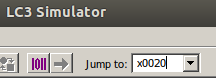
- Note the value in x0020 (It should be x0400)
- Enter x0400 in Jump to box and press enter
x0400 is the first line of the GETC TRAP routine
Quick Question: Choose One
What register(s) are save at the start of GETC at x0400?
Quick Question: Choose One
What is the last action GETC performs before the RET line at x0404?
True / False
The 2 TRAP instructions that appear at x0406 and x0407 are real TRAP instruction calls
TRAP Routines in other Instruction Architecture Sets
TRAP routines are ISA-defined. Each ISA may provide routines to support the intended/expected use of the ISA. An ISA designed for communication might include TRAP functions to connect to external systems and support basic I/O functions
Trap Vector Table
The LC-3 reserves memory addresses x0000 - x00FF for TRAP routine lookup. The TRAP Vector Table only contains references in memory locations x0020 - x0025 for the existing 6 routines. Each address in this jump table contains the location, in memory, of the start of a given TRAP function code block
Vector Table Location
LC-3 allocated memory location x0000 - x00FF for Trap Vector entries. This sets aside 256 memory location for addresses to TRAP routines. However, LC-3 only provides 6 TRAP routines, so much of the Vector Table is empty
| TRAP Vector | Pseudonym | Jump Table Address |
|---|---|---|
| x20 | GETC | x400 |
| x21 | OUT | x430 |
| x22 | PUTS | x450 |
| x23 | IN | x4A0 |
| x25 | HALT | xFD70 |
Using the Jump Table
In the above table, PUTS (TRAP x22) has a Jump Table entry at memory address x0022.
When Simulate processes a TRAP x22 instruction:
- The current PC is copied into Register R7
- Memory address x22 is read
- The value x450 is returned
- Memory address x450 is placed in the PC
- A new instruction cycle starts
- Simulate jumps to address x450 and begins processing instructions in the PUTS routine
- The last instruction in PUTS copies the value in R7 (the PC from step 1) into the PC
- A new instruction cycle starts
- Simulate jumps to the address in the user code right after the call to PUTS
- Instruction execution continues
LEA R0, MyString
PUTSAfter loading into R0 the Effective Address of the string to print, PUTS is called to do the printing
PUTS is a pseudonym for TRAP x22. The assembler to product the same OpCode and Operands for PUTS and TRAP x22
LEA R0, MyString
TRAP x22After loading into R0 the Effective Address of the string to print, TRAP x22 is called to do the printing. This runs the same routine as PUTS
True / False
If the LC-3 creators wanted to move PUTS from x0450 to x0460, they would only need to change the LC-3 Trap Vector Table's Vector for PUTS?
How the LC-3 Executes a TRAP PUTS instruction
During the execution the TRAP PUTS instruction, the LC-3 controller 'knows' the PUTS vector entry in the table is memory location x0022. The controller requested the contents of memory location x0022, and receives the address x0450
The controller stores the current PC (instruction after the TRAP PUTS instruction) in R7, and changes the PC to x0450. It then ends the instruction cycle
The next instruction cycle starts with the PC x0450, and the first line of the PUTS instruction begins a new instruction cycle
Things to note:
- The Jump Table address (x0022) for PUTS contains the address (x0450) of the first line of code for the
PUTS TRAPfunction - Before the PC is changed to x0450, the LC-3 controller stashed the current PC in R7
- Remember that R7 is used by
RETto return back to the
- Remember that R7 is used by
The PUTS Function
;PUTS Trap Function code

.ORIG x0450

; Save Registers
SavRegs	ST R7, R7_Store ; Return Address
	ST R0, R0_Store ; Pointer to String to Puts
	ST R1, R1_Store
	ST R2, R2_Store

Loop	LDR R1, R0, #0 	; Get address of first char of string
	BRz Done 					;	Char was 0, done

Wait	LDI R2, DSR 		;	Console available?
	BRzp Wait 				;	No, loop back and try again

	STI R1, DDR 			;	Write char to console

	ADD R0, R0, #1		;	Move pointer to next char in String
	BRnzp Loop 				; Loop back for next character

;Restore Registers
Done	LD R0, R0_Store
			LD R1, R1_Store
			LD R2, R2_Store
			LD R7, R7_Store

	RET

;Data Declarations-------------
	DSR		.FILL xFE04
	DDR		.FILL xFE06
	MX0462		.FILL xF3FD
	MX0463		.FILL xF3FE
	R0_Store	.FILL #0
	R1_Store	.FILL #0
	R2_Store	.FILL #0
	R7_Store	.FILL #0
.ENDThings to note:
- PUTS first stores the current contents of R7, R0, R1, R2 in memory
- R7 contains the location of the calling code's next instruction
- R0 was set in the calling code just before calling PUTS. It contains the address of the first character to be output by PUTS
- PUTS stores R0 at the start because it will change R0 as it prints each character
- The calling code may expect R0 to be set like it was before it called PUTS
- R1 and R2 are used in the execution of PUTS. Because PUTS has no way of knowing if the calling code was using these registers, it stores them to be safe
- Next PUTS gets the first character, stored in R0 by the calling code
- At any time R0 contains zero (0), PUTS will exit this loop as all characters have been written to the console
- a value zero (0) is a special case to PUTS. It is the end-of-string marker
- Expecting that R0 does not contain zero (0), PUTS waits for the console to be ready, then copies the value in R0 (an ascii number representing the character to display) to the Display Data Register
- R0 is incremented to point to the next character in the string to display
- PUTS unconditionally loop back to check for zero (0), and start the cycle again
- Once R0 is loaded with zero (0), PUTS is done displaying characters
- R7, R0, R1, and R2 original values are copied from memory back to each register
- RET is called, and the PC is loaded with the value n R7 (the calling code's next instruction)
- Execution continues ate the calling code's next instruction after PUTS was called
Add Your Own TRAP Routine
You can create your own TRAP routine and load it into Simulate, then call it from your user code
Three (3) things to Note
- You must load two extra obj files before using your TRAP routine
- These files must be loaded each time you reinitialize Simulate. The new files do not auto-load when resetting Simulate
- Your new TRAP routine can only be called using the
TRAP xnnformat
This example will create a TRAP routine that swaps the values in R0 and R1. It will be called with TRAP x2a. The actual TRAP routine function will loaded into memory starting at address x0700.
Step 1 - Pick a place in the jump table
When calling a TRAP routine, TRAP xnn uses nn as a look-up address in the jump table. So you must add your own entry into the jump table.
We will be using jump table address x2a. We must modify this address to hold the address to the start of our TRAP routine function
; Creates a new entry in the TRAP Jump Table
; Sets address x0700 into memory location x002a

.ORIG x002a ; Jump Table Address
.FILL x0700 ; Jump Table Entry
.ENDThis code will FILL memory location x002a (in the Jump Table) with x0700 (the address of the start of our TRAP routine function)
Step 2 - Load the TRAP routine function
We must load out new TRAP routine function at address x0700. So the .ORIG x700 is the first line of this function
The function will swap R0 and R1 by using R2 as temporary swap storage. The standard swap algorithm is:
Move first value into temp storage
Move second value into first value's spot
Move value in temp storage into second value's spot
;TRAP Routine to swap R0 and R1 registers

.ORIG x0700

  ST R2, SaveR2 ; Save R2 original value

  ; Swap R0 and R1, using R2 as a temp register
  ADD R2, R0, #0 ; copy R0 into R2 (temp register)
  ADD R0, R1, #0 ; copy R1 into R0
  ADD R1, R2, #0 ; copy R2 (temp) into R1

  LD R2, SaveR2 ; Restore R2 original value
  RET

SaveR2 .BLKW 1 ; Allocate space to hold R2 original value
.ENDThe function starts by storing R2 to memory. This safeguards any data that the calling program may have placed there before calling this function. It is standard practice for subroutines and TRAP routines to save all registers that will be changed.
The swap is is made by consecutive copying of data between registers. The use of ADD using the immediate value 0 is a safe way to copy data between registers without knowing what the original value was at the start.
The previously save values from R2 is restored back to R2 from memory.
Finally, RET causes execution to switch back to the calling program.
Step 3 - Call the new TRAP routine from your program
The user code calls the new TRAP routine with TRAP x2a. Recall we can't use a name like PUTS. This is because the LC-3 assembler converts any TRAP names to address. There is no way to update the assembler to convert SWAP to TRAP x2a.
.ORIG x3000

  ADD R0, R0, 15
  ADD R1, R1, -14

  TRAP x2a ; Swap R0 and R1
  HALT

.ENDThis example user code places values in R0 and R1, then calls TRAP x2a
Simulate looks up the address in memory location x2a, finds x700. Simulate places x700 in the PC, and starts a new instruction cycle.
The new TRAP routine code runs, swapping R0 and R1, then returns back to the user program at the HALT instruction. R0 and R1 will be swapped as expected.
Conclusion
TRAP Routines are defined by an ISA
Designers and implementers of an ISA write TRAP code and provide information in the ISA's Application Programming Interface (API) to help assembly programs find and use these utilities
LC-3 designers provide 6 TRAP routines
LC-3 TRAP routines can be called using the TRAP instruction
LC-3 Assembler can also identify special shortcut names for TRAP routines, to make code more understandable
Like subroutines, TRAP routines save registers when they start and restore them when complete
If they did not save registers they use, the registers would be in an unpredictable state when a TRAP returns back to your program...making it virtually unusable
Also, like subroutines, TRAP routines use RET to return control back to the program that
TRAP routines may require particular register be set before calling -or- set during execution for the user program to examine after the TRAP completes