von Neumann Model
Interacting with devices outside of the ISA
Key Concepts |
|
Introduction
Overall Architecture
These are the key elements of the von Neumann as related to the LC-3 architecture we will be using in this course. The main components are the same across different architecture However, the internal elements may be different is some cases
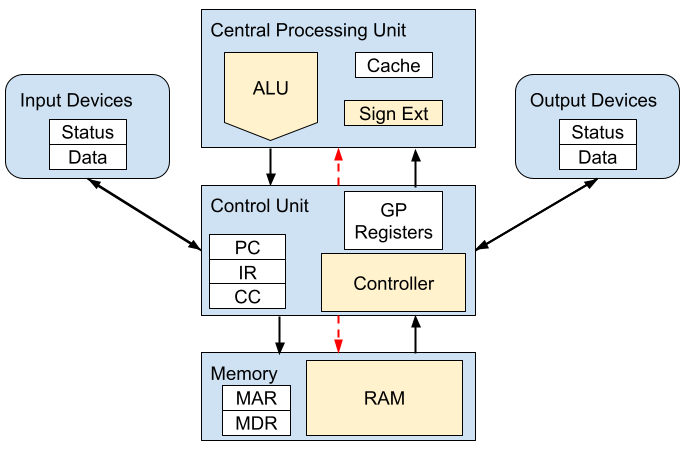
White Boxes - Registers
Yellow Boxes - Devices
Black Lines - Data Flow
Red Lines - Control Signals
Control Unit
The Control Unit is the central hub of activity in the von Neumann model. As noted on the above diagram, is it the only major component that is connected to everything else. It, in effect, orchestrates the execution of programs, requesting ALU functions, accessing Memory, and interacting with IO devices
Controller
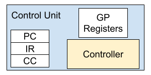
The Control knows when and how to interact to parts of the overall system to execute assembly instruction. At its heart is a State Machine containing all control and data signals that need to be issued for each ISA command
State Machine Entry Example
This is an Example of a generic ADD instruction State Entry.
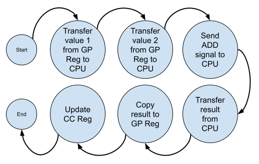
The Control Unit has decoded an assembly instruction and determined it will add two (2) values stored in the General Purpose (GP) Registers and store the result in the GP Register. When complete, the Condition Register (CC) is updated to indicate that the result was positive, negative, or zero.
- Copy the first value from a GP Register into the Data Bus to transfer it to the ALU
- Copy the second value from a GP Register into the Data Bus to transfer it to the ALU
- Send the ADD signal to the ALU
- Extract the result (placed on the Data Bus by the ALU) from the bus
- Copy result into a GP Register
- Update the CC Register based on the result's sign/value
The Controller is built and configured at the same time as the ISA/Assembly instructions. It must be able to recognize and execute every assembly instruction in the ISA. That is to say, it must have state procedures for every instruction
Managing instructions, decoding and executing them, and moving data around the system is solely the job of the Controller
Program Counter (PC)
Assembly instructions (refereed to as instructions for the remainder rof this page) are stored in Memory in a contiguous block. The controller must get instructions, one-at-a-time, so that it can execute the program
The PC contains the address in Memory of the Next Instruction. When the Controller starts the process of executing an instruction, it must first load that instruction from Memory. The PC contains the address of the next instruction
The Controller uses the address in the PC to direct Memory to load the instruction. The Controller receives the instruction into the IR register
Finally, the Controller increments the PC by 1, changing the address to the next address, before actually executing the instruction
Instruction Register (IR)
The IR hold the actual bits of the current instruction being executed. Once the controller requests the next instruction, using the PC, it receives that instruction into the IR. Now the Controller can begin examining the instruction to decide which state process to use
The Controller may need to referent different parts of the instruction while executing the state process. It can refer to the IR as needed, so that it does not need to reload the instruction from Memory
Why not just reload the instruction?
At the ISA/Microcontoller level, Memory access is slow. Depending on how the ISA interfaces with Memory, it may take multiple clock cycles to move 1 set of bit to/from Memory
Also, to reload an instruction, the controller would need to save its current state so that it can switch gears to reload the instruction. It would then need to restore the previous state to get back to work on executing the current instruction
Lastly, because the Controller advanced the PC, expecting to execute the next instruction when it completes the current one, the Controller would need to request the instruction at address PC - 1. When we discuss Branching and Subroutines we will see that doing this is not always a safe thing to do
Condition Code (CC) Register
After ALU or Memory Read instructions, the Controller will update the CC register to indicate the nature of the data that was just processed. It sets internal flags to indicate wether the data was negative, positive, or zero
CC Set for future instructions
The CC value is updates at the end of an assembly instruction execution. It can be used by the next instruction to make decisions
If the next instruction does not alter the CC, it will remain as-is for other instructions, until one is executed that changes it
While this is a fairly basic collection of information about the data, the program can use the CC to decide to loop, jump, and other actions to change program flow
TIP
This is how the LC-3 processes data condition codes
Modern ISAs will have other elements to the CC register, including Under/Overflow, Borrow/Carry, and others
General Purpose (GP) Registers
The GP registers are available for the program to use to for storing data while executing. The Controller also uses the registers with some commands, so and assembly programmer must the aware to avoid endless looping or runaway programs
As shown in the diagram at the top, the ALU and I.O devices do not access Memory directly. Only the Control Unit can access it. So an assembly programmer must write code to move data between Memory and GP registers before passing that data to the ALU or I/O
Update Data in RAM
A common pattern in assembly programs to update Memory is:
- Load data from Memory to a GP register
- Execute the ALU instruction to modify the data
- The result from the ALU is stored in a GP register
- Store the result from the GP register to Memory
In Java:
int MyVal = 17;
MyVal++;In LC-3 Assembly:
.ORIG x3000
LD R3, MyVal1; R3 will contain 1234 base 10
MyVal1 .FILL 1234CPU
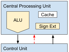
The Central Processing Unit (CPU) contains the devices and register needed to complete math and logic operations. Note that this model does not include data connected directly from Memory to the CPU. Any data in Memory that is needed for the CPU must be first loaded into the Control Unit's registers
Arithmetic Logic Unit (ALU)
The ALU contains complex circuits to perform mathematic operations such as addition, and logical operations like AND and NOT
ALUs can contain other capabilities like additional math functions and more complex logic operations. The Control Unit must know all of the ALU's capabilities and how to control the entire system when processing these operations
Cache
In order to maintain data from previous instruction or to allow buffering of data, the CPUs cache registers are used. Buffered data can improve performance when the CPU us performing several operations in the same data. The Control Unit does not need to load the same data before each instruction
Sign Ext
Some data passed to the CPU may not be the correct length (number of bits) for the ALU. The CPU can sign extend these values to ensure all data entering the ALU is formatted as required
Memory
One of the breakthrough concents of this model is general purpose memory. Previous designs called for separate data and program storage. This made the Control Unit simpler as it interacted with the two (2) memory devices separately. However, this required different hardware circuitry which made the hardware more complex
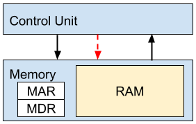
This model has one (1) memory device. The Control Unit and the program now must be aware of this and manage the information in memory correctly
RAM
The large storage array for retaining groups of bits
Each RAM location contains a number of bits. Each location contains the same number of bits. We'll refer to this amount as a word. Different architectures may use different word length. Modern computers use a power of 2 value, such as 8, 16, 32, or 64 bit word lengths
The LC-3 has a 16-bit word length
Each location in RAM has an address, This is a reference to that location, and is used by the Control Unit and program to identify a location to read or write data. The total number of addressable memory locations are also typically a power of 2 value, such 65535 (216)
The capacity (amount) of RAM is calculated by multiplying the word length by the number of locations
for the LC-3, the capacity is 16 x 65536 = 1,048,576 = 1024 KB
MAR
The Memory Address Register is used by the Control Unit to request data from Memory. The Control Unit copies a RAM address into the MAR then directs Memory to read data from that address
If the Control Unit is storing data to Memory, it places the destination RAM address in the MAR. It also copies the new value into the MDR
MDR
The Memory Data Register is used to hold a value. If the Control Unit is storing data into a RAM location, it copied the destination address into the MAR and the new value for that address in the MDR. It then directs Memory to update RAM
When requesting data from Memory, the address of the requested RAMlocation is copied into the MAR. After Memory reads the value at the address, it is copied into the MAR for the Control Unit to retrieve
Input/Output (I/O)
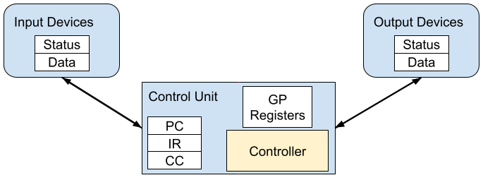
To make computers truly useful they need to have a mechanism for interfacing with the outside world. I/O devices send/receive data to/from the controller. The data can be inputs into a running program, and the program can outputs results to a device
A Little Perspective
Input and Output is from the Program’s perspective:
- A program receives data in from the keyboard (Input Device)
- A program sends data out to the monitor (Output Device)
TIP
Looking at the above diagram, note that there are no control lines. To simplify the interface, only registers are used to share status and data
I/O devices are designed and built independent of any ISA, and are typically made to operate with many different computers/ISA. That means the interface between I/O and the Controller must be simple and generic
The generic interface requires a Status and Data register to facilitate data exchange. The Status register is set to ready by the I/O device when it wants to exchange data with the Controller. The Data register is used to hold the data being exchanged
This simple interface allows any device to talk with any computers without requiring a shared clock signal or synchronization. The Control Unit can check an output device's Status register anytime, and upon finding it is Ready can copy data int o the Data register. Some time later (asynchronously) the output device will notice the new data and process it according to it's function
Conclusion
Modern computer architecture is based primarily on John von Neumann's designed. It is made up of five (5) components that manage program execution, memory access, performing math and logic operations, interfacing to the outside world
With this simple and elegant configuration, this 1945's design continues to prevail. Only as we begin the next phase, quantum computers, is von Neumann's design likely fade into history
