
Branching Instructions
Key Concepts |
|
Terms
| Term | Meaning |
|---|---|
| ADD | The LC-3 arithmetic instruction; adds two 16-bit two's-complement values and stores the result in a register, updating the CC. |
| ALU | The arithmetic and logic unit (ALU) is a component in the CPU that preforms mathematic and logical functions. |
| AND | An LC-3 logic instruction; performs a bitwise AND on two 16-bit values and stores the result in a register, updating the CC. |
| Base Register | A general-purpose register whose value is used as the starting address when computing a memory address with an offset; used by LDR and STR (encoded in IR[8:6]). |
| Branching | A technique that causes a program to change the flow of its execution; e.g., if/else and calling a function. |
| Clock Cycle | A single time segment, controlled by the computer's clock, in which circuits receive input values, process the inputs, and then produce an output. |
| Condition Code (CC) | Information about the previous instruction's result. Can indicate that the previous instruction resulted in an error/exception, overflow/underflow, or positive/zero/negative value |
| Control Unit | The part of the CPU that sequences micro-operations during instruction execution; directs the ALU, registers, and memory interface but does not perform memory reads or writes itself. |
| DR (Destination Register) | The general-purpose register designated to receive a value loaded from memory or computed by an instruction (encoded in IR[11:9]). |
| Effective Address | The final memory address computed by an instruction, for example by adding Off9 to the PC; the address stored in DR by the LEA instruction. |
| FDE Cycle | The Fetch-Decode-Execute pattern used by the CPU to execute a single instruction. |
| Indirect Address | A memory address stored at another memory location; used by LDI and STI to reach data anywhere in the full 16-bit address space, beyond the PCOffset9 range. |
| Instruction | Single executable line of code in a program. Contains OpCode and Operands. |
| IR (Instruction Register) | A CPU register that holds the instruction currently being executed; loaded from memory during the Fetch phase and decoded to identify the opcode and operands. |
| ISA | Instruction Set Architecture. LIst of all Instruction OpCode and expected Operands. |
| MAR (Memory Address Register) | A CPU register that holds the address of the memory location to be read from or written to; set by the Control Unit before each memory cycle. |
| MDR (Memory Data Register) | A CPU register that holds the data value being transferred to or from memory; written by a memory read and read by the Control Unit after a memory cycle completes. |
| Memory | Storage used by the program to save and retrieve data. This storage is external to the CPU. |
| Memory Cycle | A single read or write operation between the CPU and memory; may require one or more cycles to complete depending on memory speed. |
| Memory Unit | The hardware component responsible for reading data from and writing data to memory; operates outside the Control Unit and communicates through MAR and MDR. |
| NOT | An LC-3 logic instruction; performs a bitwise inversion (1's complement) of a 16-bit value and stores the result in a register, updating the CC. |
| Off6 | A 6-bit signed offset sign-extended to 16 bits, added to a Base Register to compute a memory address; used by LDR and STR. |
| Off9 (PCOffset9) | A 9-bit signed offset sign-extended to 16 bits, added to the PC to compute a memory address; used by LD, ST, LDI, STI, and LEA. |
| OpCode | Assembly instruction keyword as defined by the ISA. |
| Operand(s) | Assembly instruction parameters, as defined by the ISA. |
| Overflow | When an arithmetic result is too large for the available bits; for signed 16-bit values the result wraps and the sign bit may be incorrect. Reflected in the CC. |
| PC (Program Counter) | A CPU register that holds the address of the next instruction to be fetched; automatically incremented by 1 after each Fetch phase. |
| Register | Storage used by the CPU to save and retrieve data. These devices directly connected to the CPU's control device and the ALU. |
| Sign Extension (SExt) | The process of expanding a shorter bit-width value (e.g., 6-bit or 9-bit) to 16 bits by copying the sign bit into all upper bit positions, preserving the value's sign. |
| SR (Source Register) | The general-purpose register that supplies the value to be written to memory in a store instruction (encoded in IR[11:9]). |
| Subroutines | Subset of branching that has added capabilities like passing parameters, throwing exceptions, and returning results. |
| TRAP Routines | Functions that are built-in to the programming language; e.g., System.out.println() in Java. |
Introduction to Branch Instructions
The LC-3 has 1 command for branching (jumping to different lines of code). It can be used to create loops, if/else, and while loop behavior. This command is a decision point in the code. It will branch based on a register that remembers the sign of the previous instruction's result.
If the previous instruction resulted in a negative value, a BRn instruction will branch. If the register was zero or positive, the branch would not occur and normal sequential execution continues.
In this section we will review the BR instruction and look at some simple example code.
BR
LC-3 ISA Format
| OpCode | N | Z | P | PCOffset9 |
|---|---|---|---|---|
| 0000 | n | z | p | 000000000 |
Examples
BRn MyLabel1 ; If CC is in Negative Condition, branch to MyLabel1
BRz MyLabel2 ; If CC is in Zero Condition, branch to MyLabel2
BRp MyLabel3 ; If CC is in Positive Condition, branch to MyLabel3
BRnz MyLabel4 ; If CC is in Negative or Zero Condition, branch to MyLabel4
State Machine
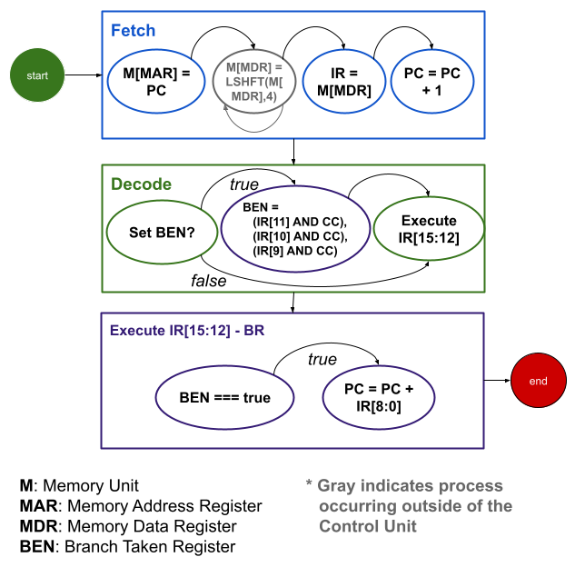
During the Decode phase, the Control Unit will determine it needs to reference the CC register. It logically compares the CC with the Instructions bits [11:9]. If any instruction bits match the CC, the BEN internal register will be set to true. This will be used during Execute.
In the Execute phase, the BEN is checked. If true, the PC register will be modifies. The instruction's PCOffset9, bits [8:0] are added to the PC and the result written back into the PC
Recall that the LC-3 Assembler will have calculated the PCOffset9, knowing that during the PC is incremented during Fetch. The value it calculates will be expecting the PC to already be referencing the next instruction in memory
If you are trying to guess what Simulate will do when it executes a BR instruction, you must also factor in the PC was incremented during fetch
Explanation
BR change the flow of an LC-3 program during execution. It is used to create behaviors like If/Else and While loops. Assembly languages typically do not have these instructions, but the code can flow like an If/Else or loop using BR.
Labels
If needed, a label is places before the instruction. It is, in effect, labeling the location os that instruction for latter use. They are any text the programmer chooses, as long as it is not a keyword or numeric vale
Labels in assembly source code are the method of denoting a particular location in the program that may be branched to from some other location in the program
Labels are human-readable text, named to help the programmer understand what the label is used for. During the assembly progress, the LC-3 Edit will convert labels to a PCOffset values needed for the BR instruction
PCOffset
The least-significant 9 bits of the BR command is a 9-bit PCOffset values. As described in the above Label section, the assembler converts the label into this PCOffset.
During assembly, the memory address of each instruction is calculated during the First Pass of the assembler. When the assembler encounters a label, it adds the label and calculates memory location of that label in a Symbol Table.
Once all addresses are calculated and all symbols have be identified, the assembler starts the Second Pass. During this process, each instruction that reference a label is identified. The assembler looks up the label in the Symbol Table, then uses the associated address to calculate an offset from the instruction's memory address.
Recall that the Program Counter (PC) register keeps track of the next instruction's memory address when the program is running.
The assembler calculates what value the PC will contain for each instruction when it is executing. It uses this value and the address of the label to create an offset from the instruction to the label. Using a 9-bit offset from the current PC value, the address calculated can be in the range of -256 to +255 memory location before the current PC.
The 9-bit offset (offset from the expected PC values at runtime) calculated is added to the instruction's operands, based on the instruction's structure. This is the 9-bit PC Offset, notes as PCOffset9 in the ISA documentation.

- The blue arrow indicates the current instruction being executed. In this example, the instruction at x3001 is being executed
- The PC is x3002 (recall the PC is incremented at fetch stage of an instruction cycle)
- MyVal1 memory label is at x3004
- MyVal1 (x3004) - PC (x3002) = 210 -or- 000000010 2
PC Offsets and the PCOffset9 binary values are shown for other instruction
The PC Offset/PCOffset9 values need to be recalculated each time the PC changes
Condition Code Register
BR reacts to the Condition Code (CC) register, which is set by the previous ALU or Memory Load instruction. After one of these instructions completes, BR will change the program flow
Examples
Conditions can be grouped on a single BR instruction
| Instruction | Conditions to Branch |
|---|---|
| BRnz | Branch is CC is Negative or Zero |
| BRzp | Branch is CC is Zero or Positive |
| BRnzp | Branch is CC is Negative or Zero or Positive |
BRnzp is an unconditional branch, because it will always branch, regardless of the CC
A shorthand for this is BR. The assembler will add the nzp for you
Condition Code Gotcha
When using multiple CC references with a BR instruction, they must appear in the n-z-p order
e.g. BRpz will cause an assembler error. This must be coded as BRzp to assemble and run
Unconditional Branch Example
True / False
-5 gets stored into Result when this code runs
Review what the code is doing after answering the question
- Code unconditionally branches to Done (x3002), skipping the instruction at X3001
- Stores the value in R0 (zero if the program was just loaded) into Result (memory location x3004)
Conditional Branch Example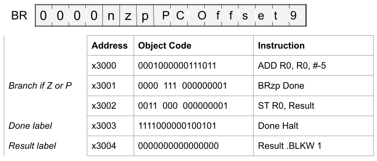
True / False
-5 gets stored into Result when this code runs
Review what the code is doing after answering the question
- R0 is set to -5
- The CC register we set to N, indicating the value was negative
- The BRzp instruction at x3001 will not cause the PC to me changes
- In effect, this instruction does nothing
- The ST instruction at x3002 executes, updating Result (x3004)
Gotchas
- When using multiple conditions, they must be in the order nzp. Swapping the order will cause an error when assembling. This is quirk of the assembler
Conclusion
Branch instruction may or may not be taken, depending on the current value in the Condition Code register. The CC register is set each time ALU or Memory Load instruction execute. The CC from the previous instruction will be used by Branch instructions.
If/Else and looping behavior can be created using labels, a control value, and the BR instruction.