Memory Access Instructions
Key Concepts |
|
Terms
| Term | Meaning |
|---|---|
| ADD | The LC-3 arithmetic instruction; adds two 16-bit two's-complement values and stores the result in a register, updating the CC. |
| ALU | The arithmetic and logic unit (ALU) is a component in the CPU that preforms mathematic and logical functions. |
| AND | An LC-3 logic instruction; performs a bitwise AND on two 16-bit values and stores the result in a register, updating the CC. |
| Base Register | A general-purpose register whose value is used as the starting address when computing a memory address with an offset; used by LDR and STR (encoded in IR[8:6]). |
| Branching | A technique that causes a program to change the flow of its execution; e.g., if/else and calling a function. |
| Clock Cycle | A single time segment, controlled by the computer's clock, in which circuits receive input values, process the inputs, and then produce an output. |
| Condition Code (CC) | Information about the previous instruction's result. Can indicate that the previous instruction resulted in an error/exception, overflow/underflow, or positive/zero/negative value |
| Control Unit | The part of the CPU that sequences micro-operations during instruction execution; directs the ALU, registers, and memory interface but does not perform memory reads or writes itself. |
| DR (Destination Register) | The general-purpose register designated to receive a value loaded from memory or computed by an instruction (encoded in IR[11:9]). |
| Effective Address | The final memory address computed by an instruction, for example by adding Off9 to the PC; the address stored in DR by the LEA instruction. |
| FDE Cycle | The Fetch-Decode-Execute pattern used by the CPU to execute a single instruction. |
| Indirect Address | A memory address stored at another memory location; used by LDI and STI to reach data anywhere in the full 16-bit address space, beyond the PCOffset9 range. |
| Instruction | Single executable line of code in a program. Contains OpCode and Operands. |
| IR (Instruction Register) | A CPU register that holds the instruction currently being executed; loaded from memory during the Fetch phase and decoded to identify the opcode and operands. |
| ISA | Instruction Set Architecture. LIst of all Instruction OpCode and expected Operands. |
| MAR (Memory Address Register) | A CPU register that holds the address of the memory location to be read from or written to; set by the Control Unit before each memory cycle. |
| MDR (Memory Data Register) | A CPU register that holds the data value being transferred to or from memory; written by a memory read and read by the Control Unit after a memory cycle completes. |
| Memory | Storage used by the program to save and retrieve data. This storage is external to the CPU. |
| Memory Cycle | A single read or write operation between the CPU and memory; may require one or more cycles to complete depending on memory speed. |
| Memory Unit | The hardware component responsible for reading data from and writing data to memory; operates outside the Control Unit and communicates through MAR and MDR. |
| NOT | An LC-3 logic instruction; performs a bitwise inversion (1's complement) of a 16-bit value and stores the result in a register, updating the CC. |
| Off6 | A 6-bit signed offset sign-extended to 16 bits, added to a Base Register to compute a memory address; used by LDR and STR. |
| Off9 (PCOffset9) | A 9-bit signed offset sign-extended to 16 bits, added to the PC to compute a memory address; used by LD, ST, LDI, STI, and LEA. |
| OpCode | Assembly instruction keyword as defined by the ISA. |
| Operand(s) | Assembly instruction parameters, as defined by the ISA. |
| Overflow | When an arithmetic result is too large for the available bits; for signed 16-bit values the result wraps and the sign bit may be incorrect. Reflected in the CC. |
| PC (Program Counter) | A CPU register that holds the address of the next instruction to be fetched; automatically incremented by 1 after each Fetch phase. |
| Register | Storage used by the CPU to save and retrieve data. These devices directly connected to the CPU's control device and the ALU. |
| Sign Extension (SExt) | The process of expanding a shorter bit-width value (e.g., 6-bit or 9-bit) to 16 bits by copying the sign bit into all upper bit positions, preserving the value's sign. |
| SR (Source Register) | The general-purpose register that supplies the value to be written to memory in a store instruction (encoded in IR[11:9]). |
| Subroutines | Subset of branching that has added capabilities like passing parameters, throwing exceptions, and returning results. |
| TRAP Routines | Functions that are built-in to the programming language; e.g., System.out.println() in Java. |
Introduction to Memory Access Instructions
Memory Access Instructions proved capability to move data between Registers and Memory (RAM).
Recall that ALU Instructions do not operate on data in memory. Before executing any instruction on data in memory it must first be loaded from memory into a register. ALU Commands only store results in registers, so it must be stored out to memory if needed.
Add Two Values in Memory
This LC-3 program adds 2 values from memory and stores it in a different memory location
.ORIG x3000
LD R1, MyVal1 ; Load first val in R1
LD R2, MyVal2 ; Load second val in R2

ADD R3, R1, R2 ; Add both vals and store in R3

ST R3, Result ; Store results of add into Result memory location

HALT
; Memory Data Declarations
MyVal1 .FILL 5
MyVal2 .FILL 6
Result .BLKW 1- The program allocates memory using the labels MyVal1, MyVal2, and Result
- MyVal1, MyVal2 are assigned values
- R1 and R2 are loaded with data from MyVal1, MyVal2 (lines 2-3)
- R1 and R2 are added together and stored in R3
- The value is R3 is stored in memory location Result
Memory Access instructions used labels to name and reference memory locations. During assembly, the label names are converted to offset values. Review Labels and PCOffsets if needed, below.
Labels Revisited
If needed, a label is places before the instruction. It is, in effect, labeling the location os that instruction for latter use. They are any text the programmer chooses, as long as it is not a keyword or numeric vale
Labels in assembly source code are the method of denoting a particular location in the program that may be branched to from some other location in the program
Labels are human-readable text, named to help the programmer understand what the label is used for. During the assembly progress, the LC-3 Edit will convert labels to a PCOffset values needed for the BR instruction
PCOffset Revisited
The least-significant 9 bits of the LD command is a 9-bit PCOffset values. As described in the above Label section, the assembler converts the label into this PCOffset.
LD
Load
LD: LC-3 ISA Format
| OpCode | DR | PCOffset |
|---|---|---|
| 0010 | 000 | 000000000 |
Examples
LD R3, MyVal1 ; Loads the value from memory location labeled MyVal1 into Register 3
LD R0, MyVal2 ; Loads the value from memory location labeled MyVal2 into Register 0
LD: State Machine
The LD instruction follows five phases
- Fetch loads the instruction from memory into the IR and increments the PC
- Decode sign-extends the 9-bit PCOffset and identifies the opcode
- Evaluate Address loads the computed address (Off9) into MAR
- Fetch Operands reads the value from that address into MDR — one or more memory cycles may be required
- Execute copies the MDR value into the destination register and updates the Condition Code
Gray nodes indicate operations performed by the Memory Unit, outside the Control Unit.
LD: Explanation
LD loads from Memory into a Register. A destination register is provided to receive the value from memory. The address to load from is provided to the Memory Interface. This address is calculated based on the PC during execution of the LD instruction.
LD: Examples
Loads value from memory location MyVal1 into Register 3
.ORIG x3000
LD R3, MyVal1; R3 will contain 1234 base 10
MyVal1 .FILL 1234Loads value from memory location MyVal2 into Register 0
.ORIG x3000
LD R0, MyVal2; R0 will contain FF base 16
MyVal2 .FILL xFFLoads value from memory location MyVal3 into Register 0
.ORIG x3000
LD R0, MyVal3; R0 will contain 111000111000 base 2
MyVal3 .FILL b111000111000LD: Gotchas
None.
ST
Store
ST: LC-3 ISA Format
| OpCode | SR | PCOffset |
|---|---|---|
| 0011 | 000 | 000000000 |
Examples
ST R3, MyVal1 ; Store value from Register 3 into memory location labeled MyVal1
ST R0, MyVal2 ; Stores the value from Register 0 into memory location labeled MyVal2
ST: State Machine
The ST instruction follows three phases:
- Fetch loads the instruction from memory into the IR and increments the PC
- Decode sign-extends the 9-bit PCOffset, reads the source register value (SR) from the register file, and identifies the opcode
- Execute loads the computed address (Off9) into MAR, copies SR into MDR, then writes MDR to the memory location at MAR — one or more memory cycles may be required
Gray nodes indicate operations performed by the Memory Unit, outside the Control Unit.
ST: Explanation
Stores a value in a Register into a Memory location. A source register is provided to supply the value to memory. The address to store to is provided to the Memory Interface. This address is calculated based on the PC during execution of the LD instruction.
ST: Examples
Store value from Register 3 into memory location MyVal1
.ORIG x3000
ADD R3, R3, #14
ST R3, MyVal1; Store value in R3 into MyVal1
MyVal1 .BLKW 1MyVal1 .BLKW 1 allocates 1 word (16-bit memory slot) and labels it MyVal1
Add 1 to a value in Memory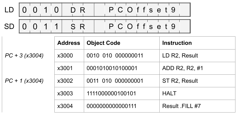
True / False
Review what the code is doing after answering the question
- The value in Result (x3004) is loaded into R2 so it can be modified
- ALU instruction cannot access Memory directly, so the value must be loaded into a register
- 1 is added to the value in R1 using ADD's immediate mode
- The updated value in R2 wit written back out to Result (x3004)
- Result (x3004) is overwritten by the ST instruction
- The programmer could have preserved the starting value by storing into a different memory location
Quick Question: Choose One
ST: Gotchas
Typically the first register in the assembly instruction is the Destination Register. With ST it is the Source Register.
LDI
Load Indirect
LDI: LC-3 ISA Format
| OpCode | DR | PCOffset |
|---|---|---|
| 1010 | 000 | 000000000 |
Examples
LDI R3, MyAddr1 ; Loads the value using the address in MyAddr1 into Register 3
LDI R0, MyAddr2 ; Loads the value using the address in MyAddr2 into Register 0
LDI: State Machine
The LDI instruction follows six phases:
- Fetch loads the instruction from memory into the IR and increments the PC
- Decode sign-extends the 9-bit PCOffset and identifies the opcode
- Evaluate Address loads the computed pointer address (Off9) into MAR
- Fetch Pointer reads the indirect address from memory into MDR — one or more memory cycles may be required — then loads that address into MAR
- Fetch Operands reads the final value from the indirect address into MDR — one or more memory cycles may be required
- Execute copies the MDR value into the destination register and updates the Condition Code
Gray nodes indicate operations performed by the Memory Unit, outside the Control Unit.
LDI: Explanation
LDI loads from Memory into a Register. A destination register is provided to receive the value from memory.
This differs from LD because it does not load from the PCOffset address. It reads PCOffset memory location for a 16-bit address. It then uses that address to load data.
The memory location containing the load address is still limited to -256 to +255 memory location before the current PC because it is a PCOffset9 value.
Using a 16-bit address to request data from memory allows the program to load from any of the 56535 memory locations in the LC-3.
LDI: Examples
Loads value from memory location contained in MyAddr1 into Register 3
.ORIG x3000
x3000 LDI R3, MyAddr1; R3 will contain value found in memory location x7000
x3001 MyAddr1 .FILL x7000 ; address containing dataAddress Value
x6FFE x0000
x6FFF x0000
x7000 x1234
x7001 x0000- Controller uses PCOffset9 value to calculate memory location that contains address to load
- Controller requests value from calculated value (x3001 in the example) from Memory Unit
- Memory Unit return value at address x3001 (x7000 in the example)
- Controller requests value at address it received from Memory Unit (x7000 in the example)
- Memory Unit returns value at x7000 (x1234 in the example)
- Controller copies received value into destination register (R3 in the example)
LDI: Gotchas
None.
STI
Store Indirect
STI: LC-3 ISA Format
| OpCode | SR | PCOffset |
|---|---|---|
| 1011 | 000 | 000000000 |
Examples
STI R3, MyAddr1 ; Stores the value in Register 3 into the address in MyAddr1
STI R0, MyAddr2 ; Stores the value in Register 0 into the address in MyAddr2
STI: State Machine
The STI instruction follows five phases:
- Fetch loads the instruction from memory into the IR and increments the PC
- Decode sign-extends the 9-bit PCOffset, reads the source register value, and identifies the opcode
- Evaluate Address loads the computed pointer address (Off9) into MAR
- Fetch Pointer reads the indirect address from memory into MDR — one or more memory cycles may be required — then loads that address into MAR
- Execute copies the source register value into MDR, then writes MDR to the memory location at MAR — one or more memory cycles may be required
Gray nodes indicate operations performed by the Memory Unit, outside the Control Unit.
STI: Explanation
Stores a value in a Register into a Memory location. A source register is provided to supply the value to memory.
This differs from SD because it does not store to the PCOffset address. It reads PCOffset memory location for a 16-bit address. It then uses that address to store data.
The memory location containing the storage address is still limited to -256 to +255 memory location before the current PC because it is a PCOffset9 value.
Using a 16-bit address to request data from memory allows the program to store to any of the 56535 memory locations in the LC-3.
STI: Examples
Store value into memory location contained in MyAddr1 from Register 3
.ORIG x3000
x3000 ADD R3, R3, #14
x3001 STI R3, MyAddr1; memory location x7000 will be updated with value found in R3
x3002 MyAddr1 .FILL x7000 ; address to updateBefore Update After Update
Address Value Address Value
x6FFE x0000 x6FFE x0000
x6FFF x0000 x6FFF x0000
x7000 x0000 x7000 x000E
x7001 x0000 x7001 x0000- Controller uses PCOffset9 value to calculate memory location that contains address to store
- Controller requests value from calculated value (x3002 in the example) from Memory Unit
- Memory Unit return value at address x3002 (x7000 in the example)
- Controller requests the Memory Unit store value in R3 into the address it received (store 1410 (000E16) into memory address x7000 in the example)
STI: Gotchas
Typically the first register in the assembly instruction is the Destination Register. With STI it is the Source Register.
LDR
Load Relative
LDR: LC-3 ISA Format
| OpCode | DR | BaseReg | Offset |
|---|---|---|---|
| 0110 | 000 | 000 | 000000 |
Examples
LDR R3, R1, #0 ; Add value in R1 with #0. Use that result as address to load value from Memory into Register 3
LDR R0, R1, #2 ; Add value in R1 with #2. Use that result as address to load value from Memory into Register 0
LDR: State Machine
The LDR instruction follows five phases:
- Fetch loads the instruction from memory into the IR and increments the PC
- Decode sign-extends the 6-bit offset and identifies the opcode
- Evaluate Address adds the base register value (IR[8:6]) to Off6 and loads the result into MAR
- Fetch Operands reads the value from that address into MDR — one or more memory cycles may be required
- Execute copies the MDR value into the destination register and updates the Condition Code
Gray nodes indicate operations performed by the Memory Unit, outside the Control Unit.
LDR: Explanation
LDR loads from Memory into a Register. A destination register is provided to receive the value from memory.
The address to load from is calculated using the 16-bit value in BaseReg added to the 6-bit offset. The value at this calculated address is loaded into the destination register.
This load instruction is similar to arrays in high-level languages. The BaseReg is the Array Name and the Offset in the Array Index.
LDR: Examples
.ORIG x3000
x3000 LEA R1, MyArray1 ; Load the address of MyArray1 into R1
x3001 LDR R3, R1, #2   ; Load MyArray1[2] into R3
x3002 MyArray1 .FILL #12 ; MyArray1[0]
x3003          .FILL #22 ; MyArray1[1]
x3004 .FILL #-7 ; MyArray1[2]The LEA instruction reads the Memory Address of MyArray1 label. It does not load that value at the Memory Address
- Controller adds value in R1 and Offset6 (x3002 + 2 in the example)
- Controller requests value from calculated value (x3004 in the example) from Memory Unit
- Memory Unit return value at address x3004 (-7 in the example)
- Controller copies value into Destination Register (R3 in the example)
LDR: Gotchas
Verify the Offset value does not cause a load beyond the know values being used
STR
Store Relative
STR: LC-3 ISA Format
| OpCode | SR | BaseReg | Offset |
|---|---|---|---|
| 0111 | 000 | 000 | 000000 |
Examples
STR R3, R1, #0 ; Add value in R1 with #0. Use that result as address to store value to Memory in Register 3
STR R0, R1, #2 ; Add value in R1 with #2. Use that result as address to store value to Memory in Register 0
STR: State Machine
The STR instruction follows four phases:
- Fetch loads the instruction from memory into the IR and increments the PC
- Decode sign-extends the 6-bit offset, reads the source register value, and identifies the opcode
- Evaluate Address adds the base register value (IR[8:6]) to Off6 and loads the result into MAR
- Execute copies the source register value into MDR, then writes MDR to the memory location at MAR — one or more memory cycles may be required
Gray nodes indicate operations performed by the Memory Unit, outside the Control Unit.
STR: Explanation
STR stores a value from a Register into Memory. A source register is provided to provide the value to memory.
The address to load from is calculated using the 16-bit value in BaseReg added to the 6-bit offset. The the destination register value is stored at this calculated address.
This store instruction is similar to arrays in high-level languages. The BaseReg is the Array Name and the Offset in the Array Index.
STR: Examples
.ORIG x3000
x3000 LEA R1, MyArray1 ; Load the address of MyArray1 into R1
x3001 ADD R3, R3, #-2  ; Place -2 in R3
x3001 STR R3, R1, #2   ; Store R3 into MyArray1[2]
x3002 MyArray1 .FILL #12 ; MyArray1[0]
x3003          .FILL #22 ; MyArray1[1]
x3004 .FILL #-7 ; MyArray1[2]. Will contain 2 after STR instruction executesThe LEA instruction reads the Memory Address of MyArray1 label. It does not load that value at the Memory Address
- Controller adds value in R1 and Offset6 (x3002 + 2 in the example)
- Controller requests the Memory Unit store value in R3 into the address it received (store 210 into memory address x3004 in the example)
- Memory Unit stores value at address x3004 (2 in the example)
LEA
Load Effective Address
LEA: LC-3 ISA Format
| OpCode | DR | PCOffset |
|---|---|---|
| 1110 | 000 | 000000000 |
Examples
LEA R3, MyVal1 ; Loads the memory address of MyVal1 into Register 3
LEA R0, MyVal2 ; Loads the memory address of MyVal2 into Register 0
LEA: State Machine
The LEA instruction follows three phases:
- Fetch loads the instruction from memory into the IR and increments the PC
- Decode sign-extends the 9-bit PCOffset and identifies the opcode
- Execute computes the effective address by adding the current PC to Off9 and stores it in the destination register — no memory access is required for the data
Gray nodes indicate operations performed by the Memory Unit, outside the Control Unit.
LEA: Explanation
LEA load the address of a label, not the value at that label. This is useful when using LDR/STR and the Trap routine PUTS, where an memory address is needed to perform some other command.
This command does not require any memory reading or writing. The PCOffset9 value is added to the PC and that result is address to store in the DR.
LEA: Examples
.ORIG x3000
x3000 LEA R3, MyVal1; R3 will contain x3001 (address of MyVal1)
x3001 MyVal1 .FILL 1234- Controller uses PCOffset9 value to calculate memory location that contains address to load
- Controller copies value from calculated value (x3001 in the example) into the Destination Register (R3 in the example)
LEA: Gotchas
None.
Conclusion
Long-term data will be stored in memory. The CPU have limited register slots to retain values after an operation completes.
A common procedure is:
- Read a value from memory into a register
- Use or modify that data while in the register
- Copy the update dat form register to memory
LC-3 has 3 variations in loading and storing values ot memory. Each has a utility based on how you will be accessing memory (where the data is in memory). LD and ST are the common instruction. The other two (2) are used in some special situations.